Comparative lead-in: two rooftops, two outcomes
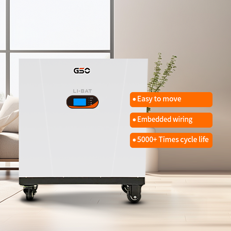
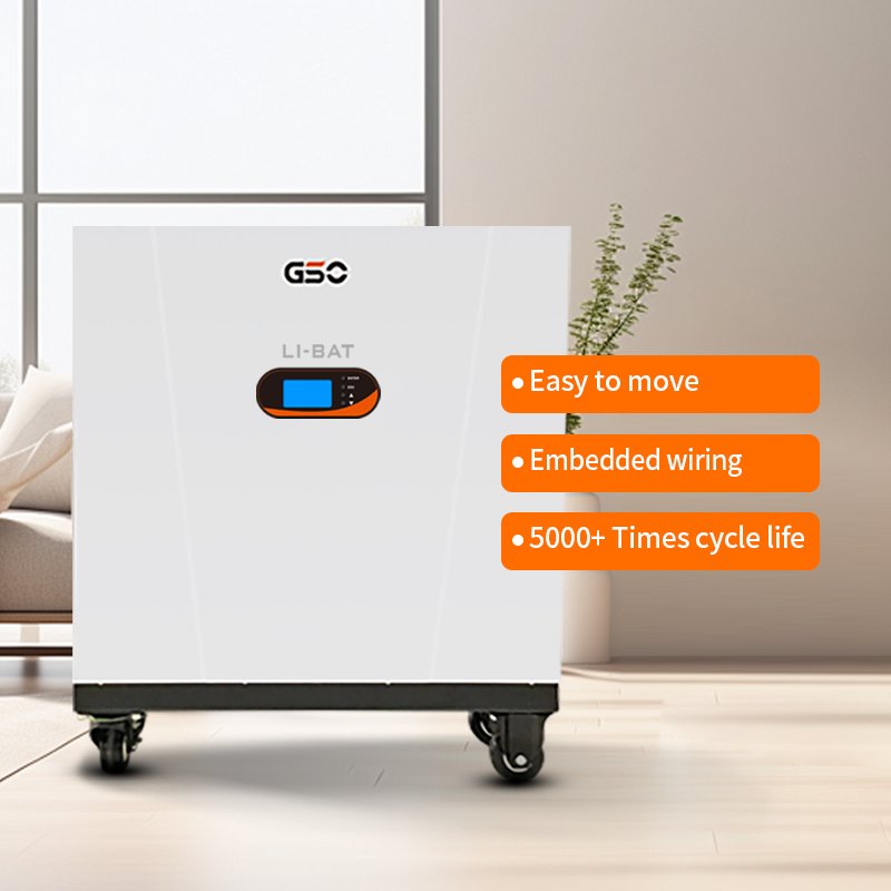
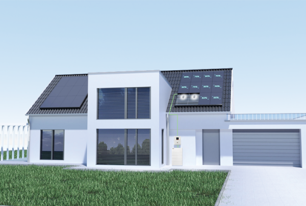
A commercial building in Sonoma County kept the lights on during a Public Safety Power Shutoff because its installer anticipated grid instability and specified robust anti-islanding settings while integrating solar battery storage early in the design. Across town another facility—cheaper components, looser settings—went dark after an inverter failed to detect grid separation. That contrast frames a comparative look at inverter safety and grid-tie performance for commercial battery systems, and it explains why choosing the right combination of inverter logic, battery chemistry, and system controls matters for uptime and compliance. For practical system choices, consider how solar battery storage handles both everyday smoothing and emergency islanding.
Why anti-islanding is non-negotiable for commercial sites
Anti-islanding prevents inverters from continuing to feed a disconnected grid, protecting utility crews and equipment. At the device level, inverter firmware uses voltage and frequency perturbation tests, and sometimes active power shifting, to detect loss of mains. For commercial grid-tie systems the stakes are higher: sustained export during an outage can damage switchgear and violate interconnection rules such as IEEE 1547. In practice, installers tune trip thresholds, ride-through parameters, and fault detection logic so inverters respond fast without nuisance trips during brief grid blips. The balance between sensitivity and reliability is a technical trade-off that defines system behavior under stress.
Chemistry trade-offs: lead acid vs lithium practicalities
Comparing batteries is core to performance. A lead acid solar battery remains attractive where upfront cost and simple maintenance are priorities; it tolerates float charge profiles and predictable state-of-charge behavior. Lithium chemistries offer higher usable capacity and longer cycle life, but they demand more sophisticated battery management system (BMS) features and thermal control. For commercial projects the choice influences inverter pairing, depth of discharge planning, and replacement schedules. When teams pair a lead-acid bank with an inverter, designers often accept lower DoD and plan for periodic equalization—practical, cost-driven decisions that shape uptime and total cost of ownership.
Inverter strategies and BMS coordination
Operational harmony between inverter and BMS is where performance is won or lost. Modern inverters provide configurable grid-tie modes: export-limited, self-consumption priority, or islanding-capable microgrid modes. The BMS must communicate state-of-charge and temperature to prevent unsafe discharge or overcharge. Installers should map fault hierarchies so the inverter does not override battery protective cutouts—safety layering, essentially. A simple misalignment—incorrect SOC thresholds or mismatched voltage windows—can produce repeated anti-islanding events or premature battery stress. And installers should document settings; field technicians benefit from clear parameter lists during commissioning—small operational clarity that pays dividends.
Field notes: common mistakes and real-world anchors
In the field, common errors repeat. Teams sometimes leave anti-islanding tests disabled during commissioning to avoid nuisance trips—an expedient that later surfaces as non-compliance. Another recurring issue is mismatched communication protocols between inverter and BMS, which leads to unsafe charge behavior. The IEEE 1547 standard and lessons from California’s Public Safety Power Shutoffs in 2019–2020 have driven utilities to tighten interconnection rules; projects that ignored those signals saw longer lead times and rework. Integrators who documented settings and ran end-to-end tests avoided most problems—real-world discipline that separates resilient installations from fragile ones.
Three golden rules for selecting systems and settings
1) Prioritize interoperability: verify inverter firmware and the battery management system speak the same language and support anti-islanding routines required by your utility. 2) Size for usable capacity not nameplate: plan around realistic depth-of-discharge and reserve margins so grid-tie behavior doesn’t force unsafe cycles. 3) Test under fault conditions: perform controlled islanding and ride-through tests during commissioning and after firmware updates. These three metrics—interoperability, usable capacity, and validated testing—measure readiness and reduce surprise failures. For teams aligning procurement and operations, pairing careful component choice with documented commissioning delivers reliable service, and that pragmatic approach is where gsopower fits as a systems partner—trusted components and clear integration guidance. –