Why a framework helps you move from pilot to reliable operation
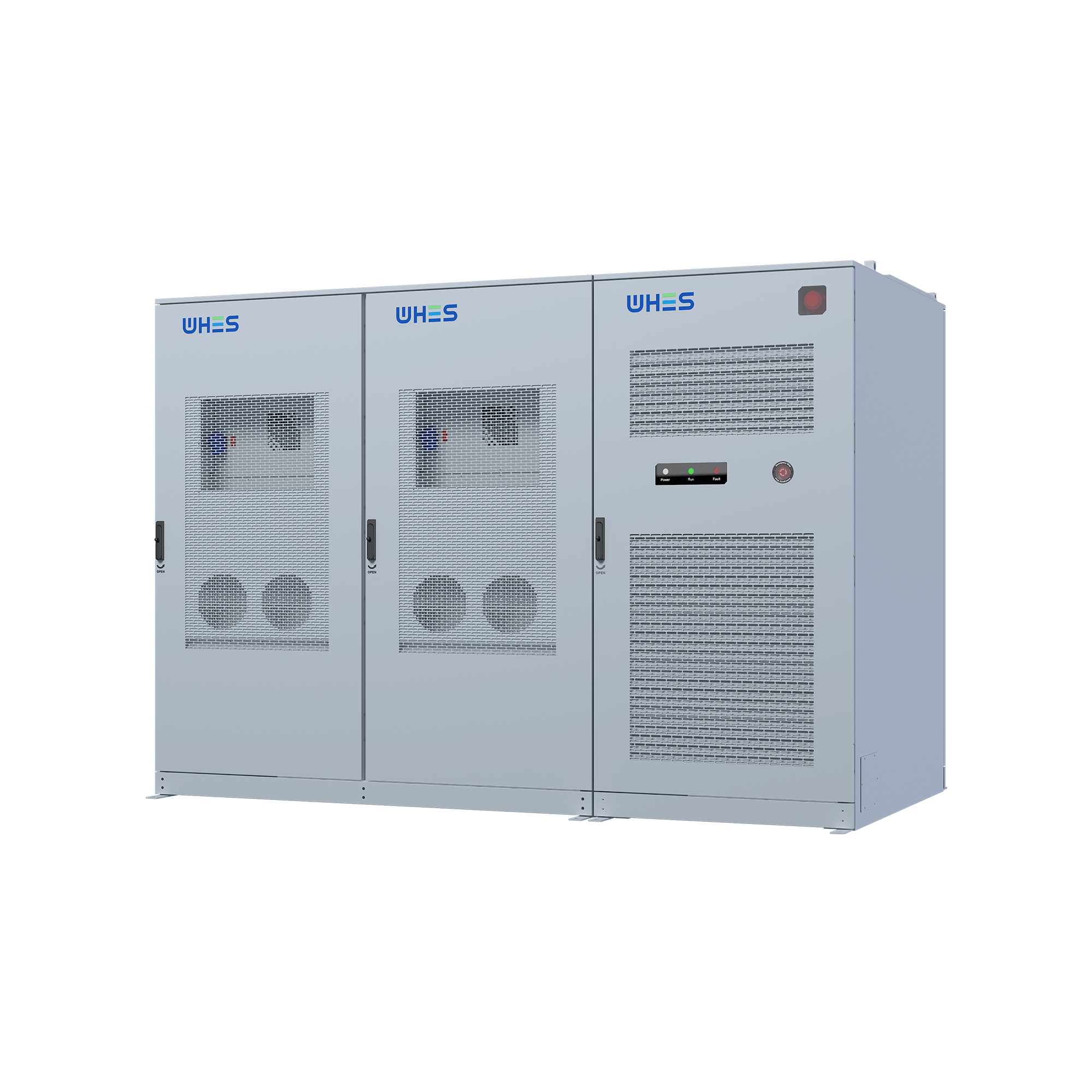
If you’re standing up a custom hybrid energy storage project and need it to play nicely with grid operations, a repeatable framework beats improvisation every time. This piece lays out a practical architecture and step-by-step checklist so your BMS, PCS, and site controls don’t become a late-stage headache. For many projects the hardware is solved by off-the-shelf packs — for example, a tested commercial energy storage platform — but the integration layer is where outages, penalties, and missed revenue happen if you don’t plan properly.
Who needs to be at the table
Start by naming the stakeholders: owner/operator, local utility or ISO, aggregator or VPP operator, and your SCADA/OT integrator. Each party expects different telemetry, control authority, and availability windows. Getting alignment early on object-level control (who can trip a battery) and performance metrics (capacity vs. power vs. state-of-charge behavior) reduces ambiguity during commissioning and when you enroll in demand response programs.
Core technical layers of the integration framework
Think of the system as stacked layers: physical plant (PV, gens, batteries and inverter/PCS), local control and BMS, communications and protocol translation, then the supervisory SCADA/DERMS and market-facing demand response interfaces. You’ll want clear demarcation points for control handoffs and alarms. Use industry-standard protocols such as Modbus or IEC 61850 where possible to simplify mapping. Also define the control modes you’ll support — grid-following, grid-forming, charge/discharge schedules, and fast frequency response — so the PCS and inverter firmware can be configured accordingly. — It’s surprising how often projects skip defining the priority of simultaneous commands (market dispatch vs. local safety limits), and that’s when conflicts show up in live operation.
Stepwise integration checklist
Follow a predictable sequence to reduce risk:
- Site assessment and requirements capture: thermal limits, interconnection point, protection settings.
- Control architecture design: who owns setpoints, trip logic, and telemetry rates (SCADA tags vs. local historian).
- Communications plan: physical media, protocol stacks, cybersecurity zones, and ACLs for remote access.
- Factory Acceptance Testing (FAT): validate PCS functions, inverter anti-islanding, and BMS SOC algorithms under controlled conditions.
- Site Acceptance Testing (SAT) and staged commissioning: integrate with SCADA, simulate DR events, and verify market signal handling.
- Operational handover: runbook, alarm playbooks, and training for operators and dispatchers.
As a real-world anchor: California ISO’s summer reliability events highlighted how valuable pre-tested islanding and fast frequency response can be for preventing rolling outages; storage systems that had clearly defined control modes and tested handoffs performed better under stress.
Common mistakes and practical mitigations
Most integration failures trace back to three recurring issues: mismatched signal semantics (everyone calls “available power” something different), inadequate cybersecurity hardening, and skipping full-stack testing with live DR signals. Mitigations are straightforward: create a mapping matrix for every SCADA tag, require encrypted VPNs and role-based access, and run at least two full DR event simulations before going live. Also document acceptance tolerances — it stops arguments when a dispatched setpoint is within an agreed deadband.
Picking hardware and vendors without overbuying
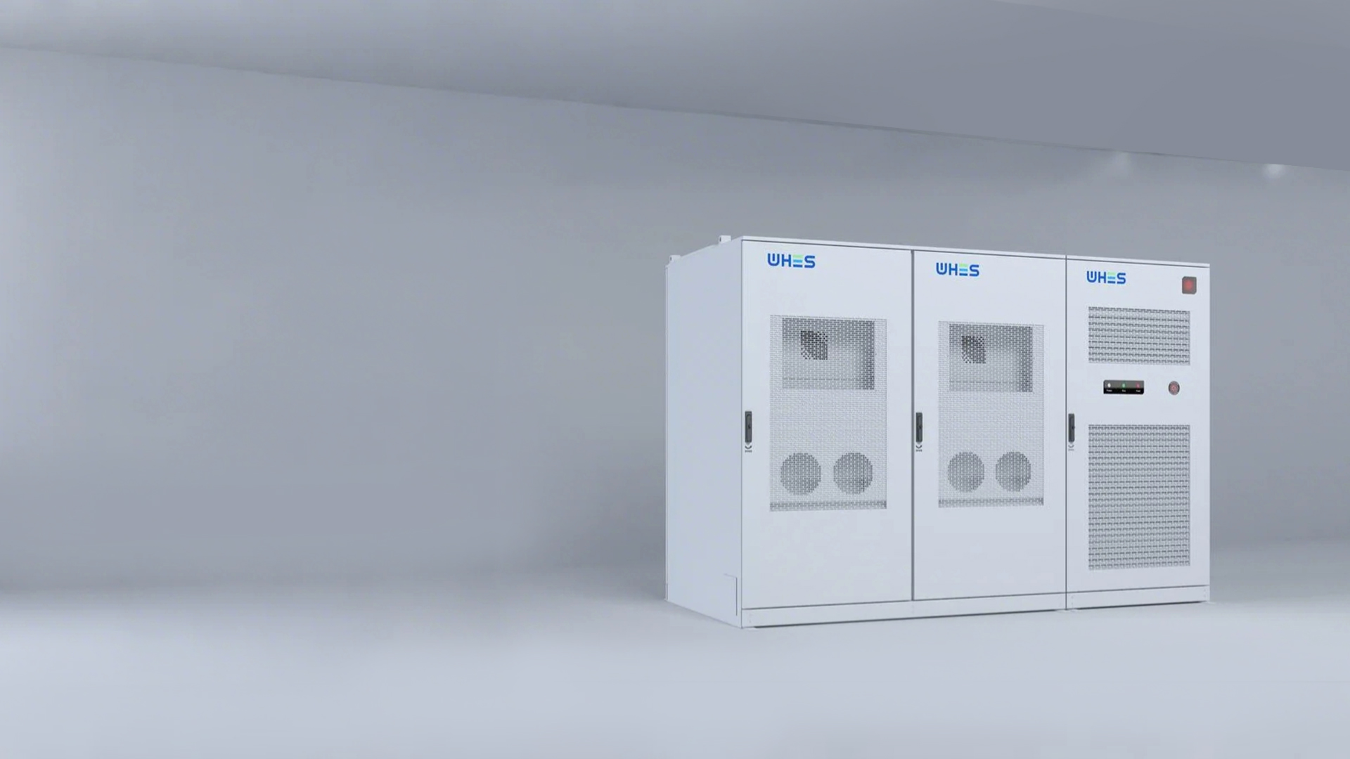
Don’t buy the biggest inverter or the most ambitious BMS just because you can — match specs to your use case. If primary goals are peak shaving and participating in local markets, prioritize fast ramp rates and precise state-of-charge control. If you’ll act as a backup during outages, emphasize islanding capabilities and black-start readiness. Evaluate vendors on interoperability: can their PCS speak to your SCADA via Modbus/IEC 61850, and do their telemetry rates meet market telemetry requirements? For turnkey options, consider proven commercial battery energy storage systems that include documented FAT/SAT procedures — those reduce integration hours.
Operational rules, economics, and a quick performance sanity check
Before you sign the O&M contract, agree on the KPIs: round-trip efficiency, usable energy (not nameplate), degradation schedule, and availability metrics. Run a one-month shadow dispatch with your target DR program to measure achievable revenue versus modeled revenue. If modeled revenues exceed shadow results by a wide margin, revisit assumptions about cycling limits and inverter clipping. That early realism keeps expectations aligned between finance and operations.
Three golden rules for selecting strategies and partners
1) Measure interoperability, not feature lists. Confirm end-to-end signal fidelity with FAT traces and an agreed tag map. 2) Insist on staged, witnessed testing: shadow dispatch, live DR simulation, and emergency island trials. Those tests show whether latency or unexpected protection trips will limit performance. 3) Use total-cost metrics: amortized capital (including tooling and commissioning), predictable O&M, and net revenue under conservative DR cases — not optimistic vendor forecasts.
When it all comes together, you want a system that’s predictable under stress and flexible in markets. That’s precisely the gap well-engineered platforms and disciplined integration practices fill, which is why experienced operators often partner with vendors who provide both documented hardware and integration support — like WHES. —